The AudioMulch Blog is written by AudioMulch's creator Ross Bencina. It discusses the in-depth nitty gritty of what AudioMulch is, how it works and what you can do with it. The blog is aimed at AudioMulch users who have mastered the basics and want to journey deeper into AudioMulch's capabilities.
If you're new to AudioMulch or want to brush up on the basics we invite you to watch our video tutorials.
ADSR (Attack Decay Sustain Release) envelopes provide a way to specify how sound synthesis parameters such as filter cutoff and gain change over time. They support the synthesis of evolving timbres and are commonly found in analog synthesizers where the envelopes are triggered by pressing keys on the keyboard.
With three ADSR envelope generators, AudioMulch's SouthPole contraption provides plenty of scope for envelope controlled filter modulation. In this post I'll demonstrate triggering the envelopes from their built-in pattern sequencers to create rhythmic patterns of filtering and gating. I'll use this functionality to synthesize some basic drum sounds and later to filter and gate samples.
Before reading on you might want to review my previous posts exploring AudioMulch's SouthPole contraption: In part 1 I introduced the basic structure of SouthPole. Then Last time I showed how the modulation mixer can be used to mix different modulation sources together to create time varying filtering.
Attack Sustain Decay Release – and Gate Duration
(If you already know what an ADSR envelope is you might want to skip down to the "ADSR enveloped filter examples -- Drums" section, but on your way past take a look at the diagrams to pick up a few insights into how SouthPole's envelope generators are wired in to the modulation mixer.)
ADSR (Attack Decay Sustain Release) envelopes are a common way to specify how sound synthesis parameters evolve over time. ADSR envelopes are simple compared to the complex envelopes of some natural sounds (waterfalls, bowed strings), and they don't offer the flexibility of AudioMulch's automation curves, but for percussive sounds and analogue synth sounds they're just the ticket. SouthPole's ADSR envelopes can be used to sweep filter cutoff, resonance and/or gain.
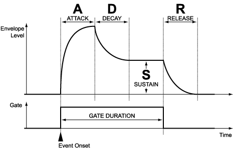
The diagram below shows how an ADSR envelope evolves over time.
ADSR timing diagram
When the envelope is triggered it sweeps to its maximum value over the Attack period, then decays to the Sustain level over the Decay period, then as the note ends the envelope returns to zero during the Release period. Note that the Attack, Decay and Release parameters are time parameters - they control the duration of their corresponding envelope segments, while the Sustain parameter controls the steady-state level that the decay segment arrives at.
SouthPole controls the timing of its envelopes using a gate (shown underneath the ADSR envelope on the diagram). The gate opens when an event starts (triggering the Attack), and closes (initiating the Release) at some later time. If the envelope was controlled by a keyboard (which it isn't in SouthPole) the gate would open when a key was pressed and close when the key was released. SouthPole provides a Gate Duration setting which determines how long the gate is open for, and thus when release starts. The Gate Duration is relative to tempo. The gate may be triggered by a pattern or an external input. In this post I'm sticking with the default pattern triggered mode where, like in some other AudioMulch contraptions, you specify a rhythmic pattern on a grid.
Envelope modulation mixing
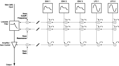
SouthPole's envelopes integrate with its modulation mixer in the same way as the LFOs I discussed last time. Their values are summed with the level of the Base parameter value and any other modulation sources according to the mix levels in the modulation mixer.
Diagram showing the SouthPole modulation mixer with envelope generators
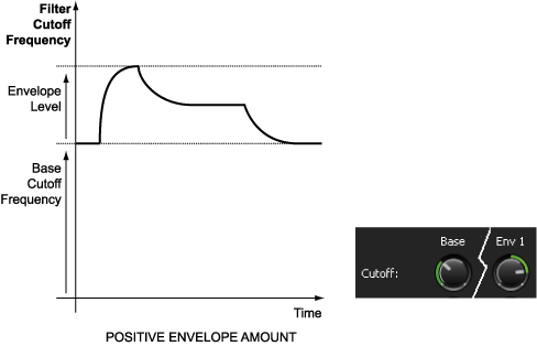
When a single envelope is used to modify, say, the filter cutoff, the Base parameter value sets the level at which the envelope starts its attack and ends its release, and the envelope modulation mixer level controls how far the attack sweeps at its highest (or lowest) point before the release begins. This also affects the scaling of the Sustain level. For a positive (clockwise) envelope amount, the evolution of the filter cutoff looks like this:
Diagram showing ADSR modulation of cutoff frequency with positive envelope level
Here's what that sounds like when filtering some white noise (the envelope is triggered 4 times):
I've made the envelope quite slow so you should be able to hear it sweep up from its Base level, then down to the Sustain level, and finally back to the Base level again during the release stage. (Actually the knob settings aren't quite the same as in the graph above, they are: Base cutoff 153 Hz and Env 1 amount 0.197)
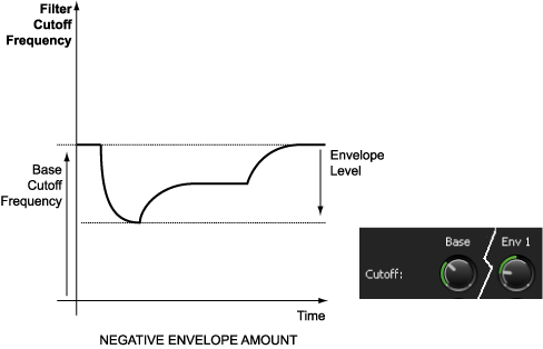
If the modulation amount is negative (the envelope modulation mix level is turned counter-clockwise) then the filter sweeps downwards below the Base cutoff frequency:
Diagram showing ADSR modulation of cutoff frequency with negative envelope level
Here's what that sounds like:
(Base cutoff 3286 Hz and Env 1 amount -0.09)
A few wild generalisations about ADSR usage
I could go on and show you how an envelope controlled filter would sound with a short attack, a fast release, a fast gate duration or varying the sustain level, or any combination of these, but the best way to get to know how the different ADSR envelope parameters affect the sound is to play with the parameters yourself. Here's a few rules of thumb to get your tweaking started:
A fast Attack time will give a punchy percussive attack. When you are modulating the filter cutoff with lots of resonance this can become a hard clicking (I use that in the kick drum synthesis example later). The Sustain level and the envelope modulation level effectively control the brightness (for cutoff frequency modulation) or loudness (for gain modulation) of the sound. If you set Sustain to zero you have an A-R envelope with the Decay parameter functioning as the release time. Short release times (especially when modulating Gain) give an abrupt end to notes, whereas a long release time can give notes a “ringing” decay which sounds like a resonant object ringing out – ringing amplitude decays was one feature of the fizzy Vince Clark/Depeche Mode synth sound in the 80s.
To get a classic analog synth filter modulation sound with SouthPole you'd usually set the base Gain and Filter Cutoff to zero (or a low value) and then modulate these with an envelope. Keep in mind that many common synth sounds use separate envelopes for filter cutoff and amplitude. Modulating resonance with an envelope is less common, but whatever resonance setting you use will usually make a big difference to the sound when an envelope is controlling the cutoff frequency.
ADSR enveloped filter examples – Drums
My last two posts focused on making melodic synth sounds with SouthPole. Today I'm going to filter noise and make some synthetic drum sounds: hi hats and kick drums. Both depend on quickly sweeping filter and amplitude envelopes to create short percussive sounds with a sharp attack and a slower release time. Here's the end result:
Hi Hats
The patch for the high-hat synthesis involves filtering white noise from a TestGen with a parameteric equaliser, then using the SouthPole to add extra filtering and amplitude enveloping:
The High-hat synthesis AudioMulch patch
The parametric equaliser filters out all of the low frequencies before they get to the SouthPole, then I used two envelope generators, Envelope 1 for the closed high hat sound, and Envelope 2 for the open high hat. The envelope generator's built-in pattern sequencers create rhythmic triggering of the envelope patterns:
Envelope 1 settings for closed high-hat (note the short release time)
Envelope 2 settings for open high-hat (short gate duration and long release time)
I used envelopes 1 and 2 to control both filter cutoff and gain. Envelope 3 adds resonance at the start of each hit for some added detail. I've also used a random LFO to slightly modulate the filter cutoff and gain of each hit to give a more dynamic feel.
High hat synthesis modulation mixer settings
As you can see, the Base filter cutoff is set quite high, so the main function of the SouthPole is to gate the white noise coming from the MParaEQ which handles most of the filtering.
Kick
The kick drum sound was made with a similar filtered noise technique. In this case the filter cutoff is ramped quickly from high-to low and its actually the filter's resonance which makes the main sound of the kick drum. Heard alone it sounds like this:
I used separate envelopes for the filter cutoff and gain. This lets me control the ringing of the kick drum using the gain envelope without affecting the tuning (controlled by the filter envelope).
Listening to the sound example above you'll notice that each kick drum hit sounds different. This is because I'm feeding the SouthPole with filtered noise. Switching the TestGen to output a low frequency (91 Hz) sine wave gives a more consistent result:
If you want to explore this further you'll find the link to download the AudioMulch document below, so read on...
Beyond filtering noise
Synthesizing drum sounds using filtered noise is great if you want that classic 70's synth drum sound but thanks to the wonders of modern technology you can also process other sounds through SouthPole. In the example below I've sequenced five different percussion samples and an electric guitar sample using a Drums contraption, and filtered these through a SouthPole contraption using variations of the high hat filter settings I described above. I've used the Metasurface to move between various parameter settings of the equalisers and SouthPole and also to fade in white noise for the original high hat sound. Similar modulations were applied for the kick drum.
Screencast showing two SouthPoles being used to gate percussion samples, controlled by the Metasurface.
You can download both the high-hat plus Drums patch and the Metasurface percussion filtering patches here. I recommend tweaking the ADSR envelope settings, gate duration and modulation amounts in the SouthPole modulation mixers to see what other filterings you can come up with. In the sample processing example there's plenty of scope for substituting different samples, sequencing different rhythmic patterns in the SouthPoles and messing with the Metasurface.
Originally I was planning to cover SouthPole's envelope trigger modes today.. but I seem to have covered enough ground for this episode, that will have to wait for next time. If you have any questions about this, or my other blog posts, please feel free to ask a question in the forums. Thanks for reading. Until next time -- Happy Mulching!
In part 1 of this series about AudioMulch's SouthPole contraption I presented the basics of resonant lowpass filtering. I gave an example of using AudioMulch's automation system to create rhythmic patterns of filtering by automating SouthPole's Base Frequency, Resonance and Gain. If you haven't read it you might want to check out part 1 here. This week's post picks up the story with an explanation of SouthPole's modulation mixing system. Then we'll look at some examples using SouthPole's LFOs (low frequency oscillators) to create various types of time-varying filtering.
Modulation mixing
Last time I talked about varying SouthPole's filter using the “Base” controls for cutoff frequency, resonance and gain. I left you with the following diagram, showing that frequency, resonance and gain can also be controlled by any of the 7 modulation sources listed across the top of the diagram:
A diagram showing the routing of all modulation sources to each basic SouthPole parameter.
The diagram lists 7 different modulation sources (Input Follower, Side Chain Follower, Envelope generators 1, 2 and 3, low frequency oscillators (LFOs)1 and 2. Each of these 7 sources is routed to all three basic parameters (cutoff, resonance, and gain). For each parameter the “Base” parameter value provides (you guessed it) a base value to which all of the modulation sources are summed (added or subtracted).
I'm not going to get around to explaining the details of each modulation source in this post, but what I do want to make clear is how the modulation sources are summed to control each basic parameter. For today, we'll just consider the Base parameters and the LFO modulation sources. Keep in mind that all of the other modulation sources are summed in exactly the same way as the LFOs. I've turned the above diagram on its side so I can show more clearly how each modulation source is summed:
A diagram showing how modulation sources are mixed to control each parameter, using LFOs 1 & 2 as examples. The circles with + signs in them indicate summing junctions.
The diagram shows that each basic parameter is controlled by the sum of its Base value and each of the modulation sources (only LFOs 1 & 2 are shown). Each modulation source is added or subtracted based on the position of the corresponding knob on the modulation mixer. To make it clear how the diagram above relates to the SouthPole user interface I've put them both side by side below, with an arrow indicating how each knob relates to the base parameter values and modulation mixing levels in the diagram.
As we saw last time, the Base parameter values sweep from low to high values, but the modulation mixing knobs sweep from -1.0 to +1.0. When a modulation mixing knob has a zero value (at 12 o'clock) its modulation source has no effect on the parameter, turning clockwise adds the associated modulation source to the corresponding parameter in varying amounts, while turning counter clockwise subtracts.
Before we get to the modulation mixing examples I'd better give a little bit of an overview of SouthPole's LFOs...
A brief sidebar about SouthPole's LFOs
As the name suggests, a Low Frequency Oscillator (LFO) oscillates slowly — typically slower than the speed we usually associate with “audio frequencies” i.e. slower than 20 cycles per second... often much slower. Thus they're useful for creating rhythmical or slowly modulating changes to the filter settings. The SouthPole contraption has two identical LFOs. Each has two basic modes: Clock Synchronous and Asynchronous. The clock synchronous mode allows you to create LFOs that stay in time with the beat (cycling every 8 bars for example) while the asynchronous mode is the more traditional free-running type oscillation where you can control the oscillation rate with a knob. There are various LFO waveforms, including a random mode which steps between random values similar to a "sample-and-hold" circuit in an analog sythesizer. When set with a clock-synchronous rate, a random LFO can be handy for randomising the filter settings or amplitudes of each note as I'll show in the final example below.
One important thing to note about all of the LFO waveforms is that they are positive DC waveforms, which means they swing from zero to one (unlike audio waveforms which alternate between negative and positive values), this makes it easy to use them with SouthPole's additive modulation mixing system: adding a sine wave LFO to the Base value causes the parameter to sweep from the Base value to a higher (or lower) value determined by the level set by the LFO's modulation mixer knob.
LFO Modulation mixing examples
So, the modulation mixing knobs on SouthPole let us add and subtract modulation sources to the base parameter values. Let's step through some simple examples. As in my last post we'll filter the output of an Arpeggiator.
An AudioMulch patch showing an Arpeggiator connected to a SouthPole connected to SoundOut
Adding and subtracting a single LFO
Here's the sound filtered with a lowpass filter, filter cutoff frequency is set to 300Hz, with no modulation. I've shown the corresponding SouthPole modulation mixer settings in the screenshot that follows the sound player:
The same sound with a slowly varying sine wave LFO modulating filter cutoff, mixed in at +0.04:
The same sound with a slowly varying sine wave LFO modulating filter cutoff, mixed in at -0.04:
Notice that in both of the previous examples I didn't change the filter cutoff Base value. With the LFO modulation amount set to +0.04 the filter sweeps upwards from the base value, with it set to -0.04 it sweeps downwards below the base value. Actually the downward sweeping example sweeps so low it filters out the input signal entirely, giving the effect of the whole sound fading in and out. It's worth starting with this setup and experimenting with how changing the LFO modulation amount changes the sound.
Mixing two LFOs
All those knobs on the SouthPole modulation mixer are there for a reason – they allow you to mix more than one modulation source together at the same time. In this example I'm going to mix a sine wave LFO and a square wave LFO. LFO 1 is the sine wave LFO, oscillating slowly as in the previous examples. LFO 2 is a faster square wave LFO which gives a rhythmic pulsing effect.
Once again here's the filtered sound with just the sine wave LFO (LFO 1) modulating the cutoff frequency downwards from the base value:
Now the filtered sound with a moderate speed square wave LFO (LFO 2) modulating filter cutoff frequency above the base value:
Finally, the filtered sound with both the slow sine wave LFO (LFO 1) and the square wave LFO (LFO 2) added together:
A more interesting example
Each modulation source can control more than one parameter. Here's an example using both a sawtooth (ramp-down) LFO (LFO 1) and a random LFO (LFO 2) to modulate all three parameters (filter cutoff, resonance and gain). The sawtooth LFO modulates the Gain to give the effect of a repeated decaying envelope. I've set both LFOs to be clock-synchronous with a quarter-note period, which locks the LFOs together creating the effect of a stream of randomly modulated notes.
The attacks are clicky due to the instant rise time of the sawtooth LFO. Usually you'd use an envelope generator to create a slightly slower attack – I'll do that in the next installment when I'll explain SouthPole's ADSR envelope generators.
Wrap up
In this post I've shown how to mix multiple modulation sources together to give more complex control over SouthPole's filter parameters. Keep in mind that the sounds presented here are the result of only one set of modulation mixing settings. Turning the knobs a bit can give quite different sonic results, as can choosing a different sound to feed through the filter. For example, you could try playing your favourite sound file through SouthPole with the settings I used today.
AudioMulch's SouthPole contraption is capable of a wide range of modulated filter effects, ranging from analog-synth style filtering and enveloping, auto-wah effects controlled by an audio input, to enveloping incoming audio according to a sequenced pattern. With all these possibilities SouthPole might seem a bit complex to begin with. Perhaps the SouthPole contraption isn't one of my most intuitive designs, but people who "get it" find it to be one of AudioMulch's most powerful contraptions.
In future posts I'll cover each SouthPole feature in detail: modulation mixing, the envelope followers, the envelope generators and their various trigger modes, and the LFOs. But I can't cover everything on one post, so this week I'm going to start at the beginning and discuss the basics: resonant low-pass filtering and the primary SouthPole parameters Base Cutoff, Resonance and Gain. It's important to understand these parameters because everything else in SouthPole builds on them.
If you really want to skip Low-pass Filter 101, scroll down to Filtering with SouthPole to check out the screencast and schematics.
Why SouthPole?
The name SouthPole was a logical choice given that the contraption was inspired by NorthPole – a free plugin from Prosoniq (apparently it's Mac only these days, but you can download version 1 for PC here ). A quick comparison of the NorthPole and SouthPole GUIs should give you some idea that SouthPole is not exactly a NorthPole clone.
User interface comparison: NorthPole 0.91b vs. AudioMulch 2.0 SouthPole
In any case, the basic idea is the same: a resonant low-pass filter with some modulation sources. (Actually NorthPole also includes a delay effect, you could easily add that in AudioMulch with a separate SDelay contraption.)
Resonant Low-pass Filter 101
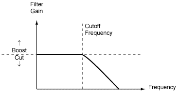
Resonant low-pass filters have been a staple of electronic sound synthesis since the birth of the analog synthesizer. As the name suggests, a low-pass filter is one which passes low frequencies (and doesn't pass high frequencies). "Low frequencies" might mean the bass parts of a sound but it's all relative – the question is "lower than what?" The frequency where the filter stops passing and starts cutting is called the Cutoff Frequency (actually this is usually defined as the point where the gain drops 3db below the pass band gain). Often the frequency response is depicted by a graph like this:
Low-pass filter frequency response graph
Higher gains run upwards, higher frequencies run to the right. The graph shows that the gain below the cutoff frequency is unity (unchanged) whereas for higher frequencies the filter progressively cuts out more and more sound.
Low-pass filters are good for creating something melow out of a bright sound source. For example filtering a bright and fizzy sound with bass in it, like a mixed pair of sawtooth oscillators from an Arpeggiator contraption:
An AudioMulch patch showing an Arpeggiator connected to a SouthPole connected to SoundOut
This "dual oscillators into a low-pass filter" is the kind of thing you'd see in an analog synthesizer. That's what I'm going to use here, but really you could filter anything: drum loops, granulated vocals, whatever. For reference, here's what the output of the Arpeggiator sounds like without filtering:
Two oscillator sawtooth Arpeggiator output
When you filter a broad-band sound with a low-pass filter with a low cutoff frequency it will sound dull and muffled like this (you might need headphones to hear this if your speakers don't reproduce much bass):
Sound of two detuned sawtooths filtered with a low-pass filter
If you sweep the cutoff frequency from low to high, the sound will get brighter as the cutoff frequency gets higher. Here's what an upwards filter sweep sounds like:
Upwards low-pass filter sweep, no resonance
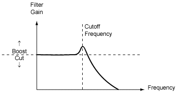
A low-pass filter passes frequencies below the cutoff frequency. But in the case of a resonant low-pass filter, frequencies around the cutoff are boosted – by how much depends on the filter's "resonance" parameter. Often you'll find a knob on analog synthesizers to control resonance (sometimes its called "Q" – an engineering term for more or less the same thing). With resonance the low-pass filter frequency response looks like this:
Resonant Low-pass Filter Frequency Response Graph
Compare this to the first frequency response graph above, notice how the gain is boosted around the cutoff frequency. With a bit of resonance, the filter sweep sounds like this:
Upwards low-pass filter sweep with resonance
Filtering with SouthPole
I don't want to scare you with a full SouthPole schematic just yet, here's the abridged version:
Simplified schematic diagram of AudioMulch's SouthPole contraption
The input sound (which enters SouthPole through the contraption's left input) is filtered through a low pass filter and has its gain (volume) controlled before coming out the audio output. You can see the three parameters Cutoff frequency, Resonance, and Gain marked along the top.
SouthPole offers many ways to control Cutoff, Resonance, and Gain, but the best place to start is with the "base values". These are the three knobs at the lower left of the contraption, handily labeled, Cutoff, Resonance, and Gain. I've circled them in red on the screenshot below:
SouthPole user interface highlighting the Base Cutoff, Resonance and Gain knobs
Try this out yourself: Gain is like a volume control. If its turned down you won't hear anything. So at first make sure the Gain is set to 0.0dB. Then you can play with the Cutoff knob to hear how it changes the sound. Finally, try adjusting the resonance. Just tweaking the resonance isn't as interesting as changing the Cutoff frequency, but sweeping the cutoff frequency with different amounts of resonance will sound quite different.
I've automated all three parameters in the screencast below. You can watch the Base Cutoff, Resonance and Gain knobs moving to see how each parameter affects the sound. The video starts with the filtered sounds you heard above, then uses faster automation to articulate a rhythmic pattern.
Screencast showing automated Base parameters in SouthPole
As you can see, there's quite a bit you can do just by automating the SouthPole's Base parameters, although often you might use SouthPole's envelope generators for this kind of rhythic sequencing.
You can download the AudioMulch document here (compatible with AudioMulch 1 and 2). Press the play button to hear the automated sequence. Make sure you hit the stop button if you want to tweak the knobs otherwise automation will override them. I also recommend that you check out HappyPenguins and the MulchOnly example files for some examples of other uses of SouthPole.
Until next time...
As I said at the beginning, SouthPole can do a lot more than I can write about in one post. But I want to leave you with one final thought: all of the other capabilities of SouthPole are concerned with providing various means to modulate the base parameters of Cutoff, Resonance and Gain. Each modulation source can be mixed to control any or all of these parameters as shown in the following diagram:
Once you get your head around it it's not so complicated. The next step is understanding how each of these modulation sources works and how they can be mixed together. I'll write more about it later, or if you can't wait, check out the help file :-) Until next time, Happy Mulching! -- Ross B.
I've learned that AudioMulch's Shaper contraption is a mystery to some, hence this week's post is devoted to illuminating the Shaper contraption...
In my last post I used the Shaper to brighten the output of a 10Harmonics contraption by adding extra harmonics. The idea was to create a broad-band pitched tone that I could then filter to sound something like human speech. That's one use for the Shaper. It can also be used to synthesize tones with changing harmonic content in a similar way to other digital synthesis methods like FM. Another way to think of the Shaper is as a type of distortion effect – and in that guise it's capable of some seriously extreme distortion.
Waveshaping 101
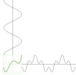
Waveshaping is the general term used to refer to the process of bending a waveform to turn it into another waveform. More specifically, it involves mapping amplitudes in an input waveform to different amplitudes in an output waveform. For a computer this is a relatively simple process: for each input sample, look at its amplitude and output the corresponding "waveshaped" output amplitude. I've tried to give an impression of this in the diagram below.
Waveshaping function diagram showing sine wave input and waveshaped output.
The wave shaping function is shown in green at the lower left of the diagram. An input sine wave is shown vertically above the shaping function. The output waveshaped waveform is shown horizontally. Grey lines indicate how the kinks in the waveshaping function correspond to input samples and kinks in the output waveform. Notice how the waveshaping function bends back at the lower left, corresponding to the inverted camel-humps in the output waveform.
The sonic results of waveshaping are not always simple or intuitively predictable. They depend on the waveshaping function (the specific mapping from input to output values), the input waveform, and also the overall amplitude of the input. This last point is a bit unusual because many audio processing effects you might be familiar with (e.g. filtering, reverb, equalisation or mixing) sound the same (aside from loudness) whether you feed in a quiet signal or a loud signal. So, when waveshaping, there are three things to keep in mind: the input waveform, the input amplitude and the waveshaping function.
Enter the Shaper Contraption
A screenshot of the Shaper contraption.
The Shaper contraption provides input gain (to adjust the input amplitude to the shaper), output gain (really just an output volume control), and some controls to adjust the harmonic weightings (we'll get to that in a second). There is also a Shaping function display which shows (surprise) a graph of the shaping function used to map input amplitudes to output amplitudes as I described above.
Perhaps you're wondering "Where did this harmonics weightings business come into the picture? Aren't we all about shaping waveforms around here?" Well, for better or worse, when you apply a waveshaping function to a waveform you change its harmonic content, often adding harmonics which weren't there before. Before you go thinking the Shaper gives you complete and precise control over exact harmonic levels with all input signals and all input amplitudes, I need to point out that the fancy harmonic weightings user interface should really be labeled "Harmonic weightings of the output waveform given a full-strengh sine wave input." If the input isn't a full-strength sine wave, the harmonic content of the output will be different. This leads to some interesting sounds as you'll soon hear.
In general, a waveshaper could use any waveshaping function (perhaps one your cousin drew by hand, or one that corresponds to the nonlinearities in a vacuum tube amplifier). But for the AudioMulch Shaper contraption to offer you the ability to specify the output harmonics weightings (given a full strength sine wave input of course) it uses a very specific waveshaping function computed from the harmonic weightings using a mathematical tool called Chebychev polynomials (named after Russian mathematician Pafnuty Lvovich Chebyshev (1821-1894)). You can read more about the math by googling "chebychev waveshaping", but you don't need to unsderstand the math to use the Shaper contraption.
Waveshaping Sinewaves Batman!
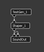
Lets feed a sine wave into the Shaper using a TestGen contraption and see what happens...
An AudioMulch patch showing a TestGen connected to a Shaper connected to SoundOut.
If the TestGen output volume is turned up full, and the Shaper input gain is turned up full then we have our "full strength sine wave input" and adjusting the harmonic weightings acts as you might expect – it adds harmonics with the relative strength shown on the harmonic weightings user interface. If we turn down the Shaper input gain we get something else, something not quite predictable, but usually something with less high frequencies. This is useful because it means variations to the Input Gain more or less correspond to perceived brightness. Also, as we adjust the input gain the timbral evolution is quite interesting – it sounds a lot like simple FM synthesis. Keep in mind that the timbre variations depend on the input amplitude and this doesn't have to be controlled by the Input Gain slider. It could be, for example, the amplitude variation caused by multiple sine waves beating against each other (as you'll see in the screencast below), or an amplitude envelope applied by another contraption (perhaps SouthPole or PulseComb).
Of course you can feed other waveforms into the Shaper too. If you stick to inputs comprised of mixed sinewaves with harmonic relationships (like I did last time using 10Harmonics) or near-harmonic relationships, like a set of carefully tuned TestGen contraptions, you'll get a harmonic output signal (i.e. it will sound like a harmonic tone). If you feed in detuned sine waves you'll get variety of outputs because the sinewaves interfere with each other in complex ways as they are waveshaped. If you're into inharmonic tones this is definitely something to explore.
Boom!
Since Shaper adds harmonics, feeding in a sound with lots of high frequencies is probably not going to work too well unless you really like nasty, rasping, high frequency hash and distortion (but please, be my guest). One sound that doesn't usually have a lot of high frequencies is the sound of a kick drum, but in some styles of music, a distorted kick drum is just what's needed. Running a kick drum through a Shaper works pretty well. For more control try using an MParaEQ to roll off high frequencies before feeding it to the shaper.
Video demonstrating the AudioMulch Shaper applied to sine waves and kick drums. (Demonstrating at 2:09 that if you're not careful it is possible to drive the Shaper into nasty clipping even after you've gone to the trouble of limiting the output with George Yohng's W1 Limiter.)
The examples I've given here are mostly of the overt synthetic distortion variety, but the Shaper can be used to add subtle, barely noticable "warmth" as well – just stick to a low input level and small amounts of the lower harmonics. For another use, check out the AudioMulch 1.0 "ShapeSynth" example file which uses Shaper to give quite a different timbre to the Bassline contraption.
That's all for now and until next time, Happy Shaping! -- Ross B.
Synthesizing the human voice is not a new idea (see for example Make's post about the Bell labs VODER). Recently I thought I'd see how far I could get making AudioMulch speak. The basic idea was to make a patch that mimics the human vocal tract, set up the parameters to make different vowel sounds and then control it using the Metasurface. My goal was to get AudioMulch to say "Audio Mulch," in the end I only got as far as "Audio." The result is pretty basic but covers some interesting ground...
The Human Vocal Tract
The human vocal tract consists of the vocal cords, which vibrate creating the pitched sounds of the voice, along with the cavities of the throat, mouth and nose which resonate the sound made by the vocal cords. Resonances created by the vocal tract (called formants) accentuate and attenuate different frequencies depending on the shape you make with your tongue and mouth – thus creating different vowels and tone colors. Non-voiced sounds are made by air turbulence (think "t" and "shhhhhh"). Here's how I simulated it with AudioMulch:
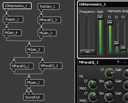
Screenshot of the voice synthesis patch.
The idea is to approximate the vibrating vocal cords using a 10Harmonics contraption fed into a Shaper to add higher harmonics, then filter that using the sweepable peaking filters in two parallel MParaEqs (parametric equalisers) to approximate the the vocal resonances. The TestGen running in to MParaEq_3 is used for the 'd' in 'Audio'.
Formant Filtering
The next task was to tune the parameters of the equalizers to create the different formant resonances. This meant setting the center frequency and bandwidth of each filter according to known values for each vowel sound. I used the values from a book about one of the early speech synthesizers called MITTalk ("From Text To Speech, The MITTALK System," Cambridge University Press, 1987) but you can find similar tables on line. There's one on the Formant wikipedia page and googling for "table of formant frequencies" brings up some interesting results for different languages. You could also work them out with a spectral analyser, but I digress.
Speech Articulation with the Metasurface
To program movements between the vowels I used AudioMulch's Metasurface window. The Metasurface provides a way to snapshot all the parameter settings in an AudioMulch document and recall them at once. More interestingly, you can use the Metasurface to smoothly slide from one set of parameter settings to another – a bit like the way the human vocal tract smoothly moves from one shape to another when you speak. AudioMulch version 2.0 will add the ability to automate the interpolation location of the Metasurface making it easy to record and refine coordinated parameter changes – I've used that feature in the video below.
For each vowel sound I wanted (and some I later didn't use) I tuned the equalisers then took a Metasurface snapshot, giving it the same name as the phonetic name of that vowel sound. I then placed each vowel in a line on the Metasurface in the order I wanted (and did quite a bit of fiddling to get it sounding right). Then I automated the Metasurface Interpolation_X parameter to scan through these snapshots moving from left to right. Then I looped the sequence. I also automated the volume of the vocal tone (MGain_4) and the noise for the 'd' sound (MGain_3) separately.
The Result
The result is shown in the following screencast. Once the original has looped a couple of times I deconstruct the Metasurface mapping, disable the automation and scan around the different formants with the mouse. [I must apologise for the apparent jerkyness of the parameter changes, the screen recorder was making the mouse input somewhat jerky.. download the patch below for the full smooth real-time control experience.]
Video showing the automated Metasurface saying "Audio".
Needless to say, the acoustics of the human vocal tract are somewhat more complex than a waveshaped oscillator and four peaking EQ filters. But it does give you an idea of the kind of complex articulations you can coordinate with the Metasurface. I've made a version of the voice synthesis patch that works with AudioMulch 1.0 (no Metasurface automation, but it can be played with the mouse). You can download it here.
If I had time to improve it I would probably play with automating the frequency of the 10Harmonics to give it more expression, and of course, finish it to say "Audio Mulch". Perhaps that will be done in time for the AudioMulch 2.0 release. Speaking of the version 2.0 release, see the version 2.0 info page for some bad news (the release has been delayed, sorry!) and some good news (I'm opening the beta program to all existing users on May 1).
After almost three years focusing on research and development it's time to start sharing the story. This blog will discuss AudioMulch and the ideas behind it, as well as offering information to assist your music making. Over the next few posts I'll also be discussing new features of the forthcoming version 2.0 release – starting today...
AudioMulch is designed for performance, whether on stage or in the studio. For me that means the user interface must support creative flow, spontaneity and improvisation. The patcher has always been central to AudioMulch; you use it to connect contraptions together, routing audio from generators to filters, effects and mixers, and finally to the output of your soundcard. I've always considered that “patching” can be part of a performance – not just a programming task you do to prepare. Some AudioMulch users take live-patching to the extreme and give whole performances building a patch from nothing!
Even if you're not into extreme-live-patching, routing and re-patching audio signals is central to the AudioMulch workflow – it's a big part of being creative with the software. For some time I've wanted to make AudioMulch easier to use and better suited to live performance. Out of this desire, and lengthly discussions with fellow AudioMulch users, I developed a new patcher for AudioMulch 2.0.
With AudioMulch 1.0 every patch cord must be connected manually. Inserting a contraption in between two existing contraptions often involves deleting the connecting patch cords and then creating new ones. There are a few tricks, but overall patching in AudioMulch 1.0 can become a bit tedious.
The AudioMulch 2.0 patcher makes patching easier. To start with, AudioMulch 2.0 includes a side-bar contraptions palette. You can drag contraptions from the palette into the patcher to create them without the need to navigate the “New Contraption” right-click menu.
The AudioMulch 2.0 Patcher
What's more, if you drag a new contraption over an existing one it will auto-connect, inserting it into the signal flow automatically without the need for you to manually delete and re-connect patch cords. If necessary other connected contraptions will move out of the way. (Incidentally, in AudioMulch 1.0 you can do a similar thing using the right-click menu to create new contraptions using the “Insert Before” and “Insert After” menus, all this right-click functionality is also available in AudioMulch 2.0.)
The AudioMulch 2.0 patcher allows you to grab patch cord endpoints disconnect them from one contraption port and re-connect them somewhere else – you can even grab whole “bundles” of patch cords and move them together.
Screencast: Inserting contraptions into the signal flow and reconnecting bundles of patch cords
There are also a number of keyboard modifiers which make it easy to create multiple connections at once. I'll explain this in a future post.
In summary, the AudioMulch 2.0 patcher will make it much easier to rapidly assemble patches and make creative patching decisions during performance.
Thanks for reading. I hope you found this post informative. I'll be writing a post about once a week, so please come back and check it out. Oh, and Happy Mulching!
-- Ross B.
 Subscribe